Homework 2: Pipelined Processors in Ripes
Due: Wednesday, 2/18 at 11pm
Overview
In class, we implemented a single-stage CPU in Ripes, and then used the concept of instruction-level parallelism to create a five-stage pipelined CPU. In this assignment, you will explore the consequences of creating four- and six- stage CPUs. You will identify data and control hazards, implement the forwarding and hazard units for the CPUs, and perform some analysis about the relative performance of the pipelines.
Stencil code
We will be working in our course Ripes repo, which is already on the Docker containers in the provided dev environment. If you haven’t already, you can get your own copy at this Github Classroom link. Just like in HW1, build Ripes using make (optionally with -j4 or -j8 to speed it up). The files you will be working on are in the src/processors/CS1952y/four_stage_cpu and src/processors/CS1952y/six_stage_cpu subdirectories. The processor circuits, including the completed decode/control units from the single-stage processor, are provided for you. You will be completing the hazard and forwarding units. Remember that all of the code for the single-stage and five-stage CPUs we built in class, including intermediate steps, has been provided for you in this repo, as a reference.
Don’t forget the Ripes/RISC-V resources linked on the course page, and the lecture notes linked on the schedule page! Before starting the homework, read through part 3 of the pipelining notes: this is “Part 0” of the homework and gives context to the forwarding units you will be implementing.
Grading information
You will be graded on the functionality and performance of your hazard and forwarding units, as well as your analysis. See the handin section for a list of files to turn in. We expose some basic Autograder tests, but it’s up to you to thoroughly test your pipelines for how they respond to hazards. Keep in mind that the actual amount of code you have to write for this assignment is not that high: the majority of the time spent will be reasoning about hazards and resolving design decisions. The analysis questions are non-trivial, so set aside time for them.
The processors should be able to handle every instruction on page 104 of the RISC-V spec (the 32I base instruction set table) except for FENCE, FENCE.I, ECALL, EBREAK, CSRRW CSRRS, CSRRC, CSRRWI, CSRRSI, CSRRCI.
The pipelines
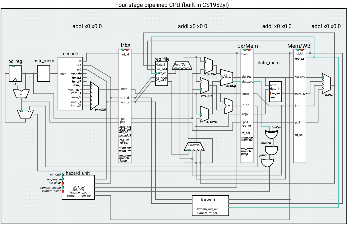
Four-stage pipeline: This processor gets rid of the ID stage, putting the decoding and control into the “I” (previously IF) stage, and the register file read into the Ex stage (the write is still in WB). Reading from the register file is assumed to be fast, so moving the register file to the execute stage might make sense if the memory operations (on data/instruction memory) are the bottleneck.
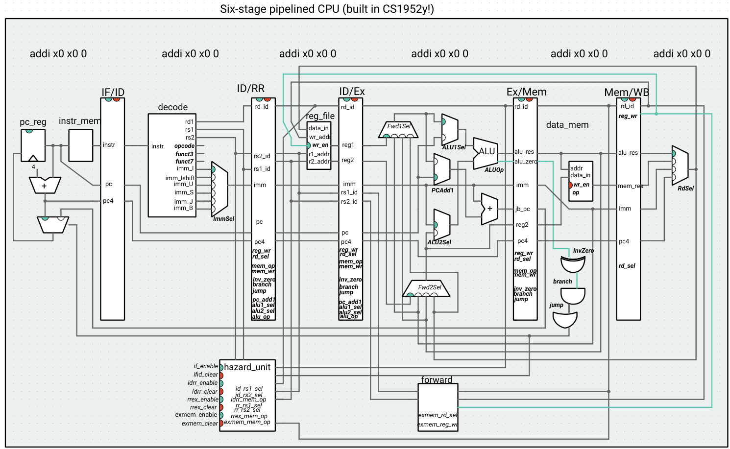
Six-stage pipeline: This processor attempts to compensate for the fact that memory read/writes might be slow by pipelining the memory unit (we’ll start exploring other ways to increase memory access throughput in class). Memory is split into two stages. An instruction requests a memory access in Mem1, and receives the result after the subsequent cycle. This might mean that two load/store instructions are using the data memory unit at one time (one in Mem1, the other in Mem2). However, we assume that the memory unit will process thee in order, e.g. a store followed by a load at the same address will not introduce a hazard.
Tips
There are a lot of wires and signals in the images above. Don’t panic! These are complicated circuit because CPUs are complicated little pieces of electronics (in fact, as we’ll see, modern processors even more so), but here are some tips to navigate the circuitry:
- Just like we did in class, you can trace an instruction by looking at the control signals that are high (look at the highlighted indicator on each multiplexer). Get to know each processor by running a few instructions at a time and observing their journey through the pipeline.
- If you don’t know where a wire goes, click on it to highlight it. You can also take a look at the
cs1952y4s_cpuandcs1952y6s_cpucode to see how the inputs/outputs of the components connect to each other. - We deliberately gave you more inputs to the forward and hazard units than you might need – do part 1 first, without thinking about the signals, and then think about how your drawings in part 1 can help you identify the logic you need to write in part 2.
- Make use of both the processor view and editor view to see which instructions are in which stage of the pipeline. You can place breakpoints if you want to debug longer programs, and you can right-click on any input/output port to display its value if you need to see a specific signal in more detail – read the Ripes documentation (linked on the resources page) for more information on navigating Ripes.
In terms of the flow of the assignment: Part 1 depends on Part 0, and Part 2 depends on Part 1. Analysis Q1 depends on Part 2. Analysis Q2 can be done indpendently of the previous parts. Analysis Q3/4 can also technically be done independently of at least parts 1-2, but will benefit greatly from you having worked through those parts first. As we said, the number of lines of code are not very large, but that doesn’t mean this assignment is quick/easy. Most of you will not have debugged a circuit of this complexity in simulation before. Start on parts 0-1 early to give yourself time for conceptual understanding.
Part 0:
Read through part 3 of the pipelining notes, which explains how to resolve data hazards with the help of forwarding (something you will be doing for the processors in this assignment).
Part 1: Identifying hazards
For each pipeline, draw two pipeline diagrams (four diagrams total), similar to those in the pipelining notes for the 5s processor. The first diagram should show what happens with a control hazard (branch and/or jump instruction). The second diagram should show the possible data hazards and how they’re resolved with forwarding and/or stalling. Put all of the diagrams in a single PDF file (to make them easier to grade).
Your diagrams should be structured similarly to the ones in the pipelining notes/the textbook. Make sure that they include the corresponding RISC-V instructions, and make sure it is clear how each hazard is resolved (via flush, forward, or stall).
Note that you can confirm that code contains a hazard by running it on the given processors (without the forwarding/hazard units) and observing that an incorrect side effect (register or memory write) occurs.
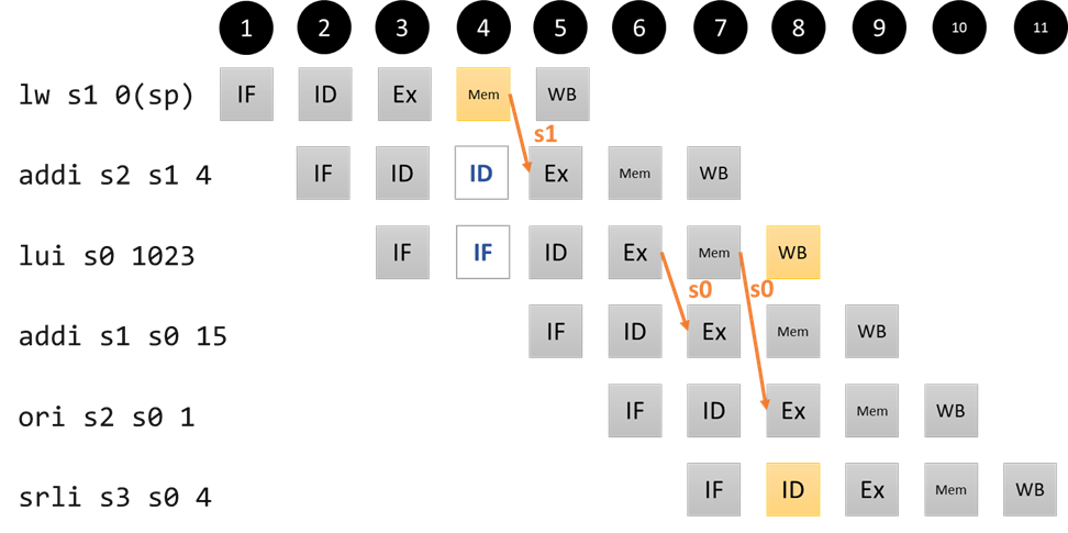
For the control hazard, we are looking for a diagram similar to the one in part 2 of the pipelining notes. For the data hazards, we are looking for a single diagram that communicates all of the possible mechanisms used to resolve hazards. This will likely mean that the example program in your diagram will contain multiple hazards. For our 5-stage pipeline, something like this would be acceptable: Note that this diagram is missing some of the detailed examples from the notes. It gets across the situation that warrants stalling, and it gets across the two different forwarding pathways (ExMem register to Ex stage and MemWB register/RdSel mux to Ex stage), but it doesn't distinguish between all of the sources of the data being forwarded, how "ties" are broken, what sorts of programs *do not* create hazards, etc. It will be up to you to think through these details in order to pass our autograder tests, some of which are hidden for this reason.What are we looking for?
You can use any software you want to draw the pipeline diagrams. This is the Google Slides link with the diagrams from the notes. [This]](/assets/docs/pipeline_diags.pptx) is a template we used for earlier version of the diagrams in Powerpoint.
Part 2: Implementing the forwarding and hazard units
Using your observations in part 1, complete the code for the forwarding and hazard units. A large part of this task will be understanding the circuit and control signals, based on what we saw in lecture for the single- and five-stage CPUs. Do not modify any files besides cs1952y[4/6]s_[forward/hazard].h – these will be the only Ripes files you turn in, which our autograder will slot into the Ripes repo in order to build your processor. Also, do not add/remove any inputs/outputs from these files. You might find that some input signals should remain unused or some outputs should remain high/low/not use a given Mux selection signal. That’s part of the design challenge of this homework!
Note that it is possible to create a really conservative CPU that just stalls whenever a hazard of any sort is detected. While this would be a working processor (as long as stalling is implemented correctly), it would not be a very efficient processor. Your implementation grade will come not just from the correctness of your processor but from your processors’ ability to stall only when necessary in order to avoid degrading performance.
Part 3: Analysis
Question 1:
One goal of this homework is for you to identify when deeper pipelining is desirable and when the added complexity may be unnecessary. Write two different programs, each of which uses at least one of each instruction in the register/register, register/immediate, memory, and control transfer categories (so, at least four different instructions). The programs should also run for 50 cycles or more. Assume that the 6-stage pipeline clock cycle time is 75% of the 4-stage pipeline clock cycle time. One program should result in a lower execution time for the four-stage pipeline, and the other program should result in a lower execution time for the six-stage pipeline. You will turn these programs into gradescope as 4s_better.s and 6s_better.s. In your PDF file, for each program, briefly explain why the program performs better on one pipeline over the other.
Question 2: (These numbers are adapted from Exercise 4.7 of P&H)
Assume the following latencies for each circuit component (we’re ignoring the hazard/forwarding unit for simplicity):
- Instruction memory/Data memory: 250ps
- Register file: 150ps
- Mux: 25ps
- ALU: 150ps
- Adder: 100ps
- Single logic gate: 10ps
- Extract bits: 5ps
- Sign extend: 10ps
- Combinational logic units (control): 50ps
- Register read: 30ps
- Register setup: 20ps
“Register read” is the time needed after the rising clock edge for the new register value to appear on the output. This value applies to the PC and the pipeline registers. “Register setup” is the amount of time a register’s data input must be stable before the rising edge of the clock. This value applies to the PC and the pipeline registers. The register file doesn’t use register read/setup – all of its operation (including bypass) is encapsulated in the 150ps figure above.
Based on these numbers, what is the minimum clock cycle time of the five stage CPU from the notes? In your PDF file, show your work by indicating the worst-case path for each cycle on the diagram or by writing it out.
Question 3: The only reason data memory depends on the ALU is for address computation. If we required our load and store instructions to have 0 in the immediate field (e.g. lw rd 0(rs1)), then the data memory unit could take the rs1 value (instead of the ALU output) as the addreess input, and any given instruction would never use both the ALU and data memory, so we could place both units in a single “EM” (Execute-Memory) stage:
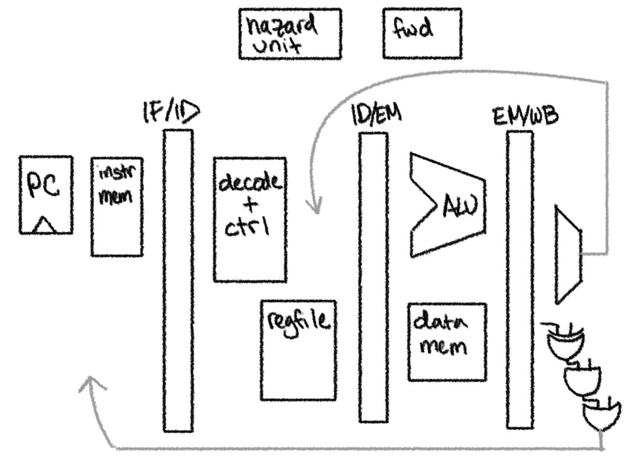
(note that this diagram is a “cartoon” with the wires, PC adders, and a lot of the multiplexers left off).
One way to ship a CPU like this is to produce a brand new assembler that synthesizes a load/store with an immediate offset into two instructions: lw rd imm(rs1) becomes addi rs1 rs1 imm; lw rd 0(rs1). This is a bad idea for two reasons: it means existing RISC-V binaries/toolchains that don’t use your special assembler won’t work with your CPU, so people will be reluctant to buy your CPU because it will require additional work on their part; and it can potentially break program correctness (consider a program like lw s0 4(t0); addi t1 t0 8. If the first instruction gets synthesized to addi t0 t0 4; lw s0 0(t0), then the value of t0 going into the addi t1 t0 8 instruction will not be the intended value). Our assembler could solve this second issue by subtracting the immediate back from rs1 after performing the load/store, but now we’ve potentially tripled the number of cycles that a load/store takes by padding it with two instructions. The first issue still stands.
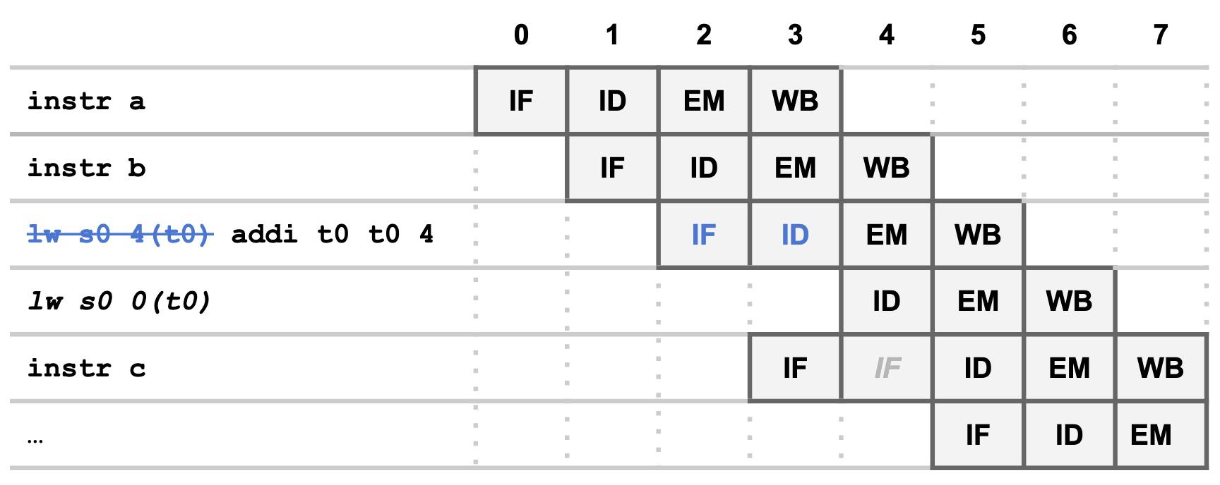
Another approach is to apply what we learned from our hazard unit when working on pipelined processors. In the pipeline diagram of step 4 of the pipelining notes, we set the enable signal of the PC register and the IF/ID pipeline register to 0, which meant that two instructions basically repeated those stages for another clock cycle, allowing the earlier instructions to advance ahead to allow for hazard resolution via forwarding. In order to prevent a stalled instruction writing twice, we cleared the ID/Ex pipeline register, which meant a nop percolated through the pipeline. What if we did something similar to make our CPU execute loads/stores with immediates as two instructions, but by inserting an instruction instead of clearing? In the pipeline diagram below, the lw instruction turns into an addi after the ID stage. Meanwhile, instr c gets delayed by a cycle while a new lw instruction with a 0 for the immediate gets inserted.
Note: we implemented this CPU ourselves just to check that the idea works. It does! But we’re not going to make you do that work, because it would be a whole assignment on its own. It also turns out that the notion of CPUs breaking up instructions into manageable chunks is not a new one. We’ll come back to this when we talk about micro-ops.
Say we were implementing a new unit to perform this operation. From the diagram above, at the very least, this unit needs to detect a memory operation with a non-zero immediate in the ID stage and: a) drive enable low for the PC register; b) inject a new instruction for the next ID cycle; c) intercept and change the signals going into the next EM cycle (in the diagram above, all of these would happen during cycle 3 and take effect in cycle 4). In your PDF, answer:
- What would we have to add to the circuit in order to inject a new instruction for the next ID cycle?
- Which signals would we have to intercept going into the next EM cycle? How do we make sure that the fake addi instruction actually has no effect (t0 doesn’t get written to in the above pipeline diagram)?
- How will the forwarding unit help us?
Question 4: (this builds on question 3) In your PDF, explain the performance tradeoffs of the CPU in Q3 vs. our finished 5-stage pipeline CPU on different workloads. Consider:
- How the CPI differs for large programs running on each processor
- How the approximate clock cycle time differs for each processor (assume each element, such as the ALU, has the same latency in both CPUs.)
- The presence/absence of stalls on different workloads on each processor (what sort of workload would you want to run on the new processor? On the 5-stage CPU?)
Part 4: Reflection
At the end of your pdf, include your answers to the following questions. Questions 2 and 3 are optional (but highly recommended). Question 1 should have a good-faith effort response.
- What were your main takeaways from this assignment?
- What suggestions do you have for improving the assignment in the future?
- What questions do you still have about pipelining/CPU design?
Handin
Your submission should include the following files, all made to the same Gradescope submission:
- Your implementations for
cs1952y[4/6]s_[forward/hazard].h(four files) from Part 2. - Your
4s_better.sand6s_better.sprograms from Part 3. - Your pdf, which should include: your answers to part 1, your answers to part 3, and your reflection from part 4.
Quiz prep
These are the sorts of questions you might expect to appear on the quiz that follows this homework.
- Given an existing RISC-V instruction, what will be the value of the control signals (multiplexer selection, write enables, etc) in our single-cycle CPU when executing that instruction? (similar to P&H ex. 4.1)
- Given a brand-new RISC-V instruction, what changes would we have to make to our single-cycle CPU in order to implement that instrucrtion? (similar to P&H ex. 4.11-4.13)
- Given a program and our 5-stage processor, what are the data hazards in the program? Which ones could be resolved by forwarding? Which ones need to be resolved by forwarding + stalling?
- Given a program and a 5-stage processor that has an incomplete/missing hazard/forwarding unit, what would the output of the program be? Could you insert NOP(s) to make the program produce a correct output (similar to P&H ex. 4.20)?
Note: if you’re looking through the P&H chapter 4 exercises for practice, ignore the ones about branch prediction, exceptions, and multiple-issue. We’ll get to these topics later on in the course. Any questions about specific processors will be based off of the 1c and 5s CPUs in the class notes, not the diagrams in P&H (for example, try to do ex. 4.1 based on our final single-cycle CPU in the notes).
Changelog
- 2/9 5:25 pm: Clarified that the 4-stage pipeline register file write still happens in WB
- 2/10 3:03 pm: Fully removed hazard/forwarding units from analysis Q1
- 2/11 12:00 pm: Added clarification on CPUs for quiz
This will be updated whenever any clarifications have been added to this assignment. See also the FAQ on Ed!