Building a five-stage pipelined CPU in Ripes (Part 3 -- Data hazards)
Previously: Five-stage CPU part 2
Step 3: Handling data hazards using forwarding
A data hazard occurs when an instruction needs data that hasn’t been written back to the register file (or memory) yet. We could handle data hazards similarly to how we handle control hazards, by causing the pipeline to be idle until the dependent computation reaches the WB stage (this would be called a “stall” or “bubble” rather than a “flush,” since we’d be inserting nops in between instructions instead of clearing existing instructions). It turns out that we’ll have to do this sometimes, but we can avoid idleness in many circumstances using a strategy called forwarding, where we simply bypass the register file and move data to the correct place the moment it is available. For an instruction that uses the ALU, the result is available at the end of the Ex stage, and for an instruction that uses data memory, the result is available at the end of the Mem stage.
Let’s examine data hazards concretely using small snippets of code. In the following examples, we load in some initial data to some registers, and then include nops so that we don’t have to worry about hazards when initializing registers.
Near- and non-hazards
In order to build up an intuition for code that will cause hazards, let’s take a look at two instances that look like they might be hazardous (dependent instructions that are spaced fewer than 5 instructions apart, that is, that will be in-flight in different stages of the pipeline at the same time) but can either be resolved using a tiny tweak to the register file or don’t create any hazards at all.
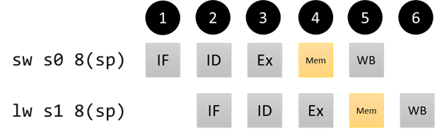
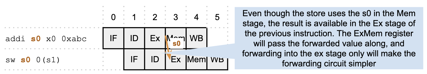
Example 1: Store/load dependency
addi s0 x0 3
nop
nop
nop
nop
sw s0 8(sp) # data @(sp + 8): 3
lw s1 8(sp)  # s1 = 3
We can run this code right now and get the correct result. This is because, in our hardware, the data memory unit stores data within one cycle, e.g. by the time the sw finishes its Mem stage. In the next cycle, when the lw instruction starts its Mem stage, the data is available. Hence, the store/load scenario is not a data hazard in this pipeline. However, if some subsequent instruction needed the value of s1 before the lw instruction finished its WB stage, we would have a hazard, which we’ll look at in a bit.
Pipeline diagram for store/load non-hazard
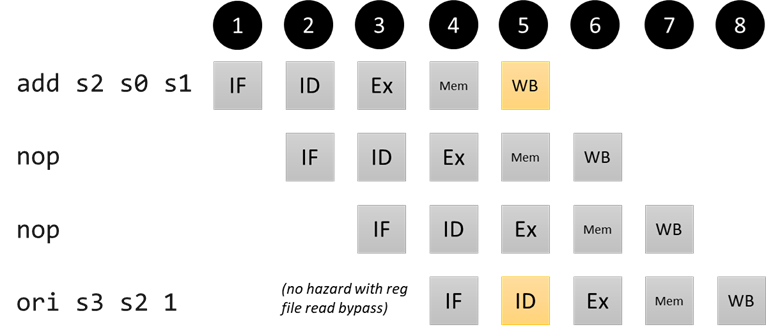
Example 2: Ex-stage dependency 3 instructions ago
addi s0 x0 3
addi s1 x0 5
nop
nop
nop
add s2 s0 s1 # s2 = 3 + 5 = 8
nop
nop
ori s3 s2 1 # s3 = 8 | 1 = 9
If we run this code with our pipeline as-is, we do get an erroneous result. However, notice that the add instruction will be in the WB stage when the ori instruction is in the ID stage – both instructions are using the register file at this cycle. When we were going through the single-stage pipeline, we saw that the result of the writeback was available in the next cycle. In modern hardware, we could instead opt to use a register file technology where writes to registers happen at the beginning of the cycle and reads from registers happen at the end, so that the effect of the ori writeback to s2 takes effect right before the add reads the value of s2. (In practice, this might make the register file a little slower, but it is generally safe to assume that a slowed down ID stage will still be faster than the more complex ALU/memory units of the IF, Ex, and Mem stages, so there wouldn’t be an effect on the clock period of the processor). For us in simulation, all we need to do is change the readBypass line when initializing the register file in the CPU (see src/processors/RISC-V/rv_registerfile.h if curious about the implementation):
SUBCOMPONENT(registers, TYPE(RegisterFile<XLEN, true>));
Pipeline diagram for near-hazard
Ex/Ex hazards
While we were able to solve the issue above with a small change to the register file hardware, the only reason we were able to do that was because the add instruction had reached the WB stage right when the ori read the data in register s2 from the register file (in the ID stage). What if there were instructions in the pipeline that needed the value of s2 before the add had reached WB? For example:
addi s0 x0 3
addi s1 x0 5
nop
nop
nop
add s2 s0 s1 # s2 = 3 + 5 = 8
subi s3 s2 4 # s3 = 8 - 4 = 4; s2 dependency 1 instr ago
sw s1 0x7fc(s2) # 5 @ address 0x804; s2 dependency 2 instrs ago
These types of hazards are called Ex/Ex hazards: the depending instruction’s result (the add) is available at the end of its Ex stage; while the dependent instructions need the data going into their Ex stages (to perform the subi or the sw address computation using the ALU).
The key insight is that the depending result is available before the instruction reaches its WB stage. What if we had some extra wires, multiplexers, and control logic to route the data that the add instruction will eventually write to s2 into the input of the ALU in the Ex stage? That would be called forwarding.
Pipeline diagram for our Ex/Ex hazards including forwarding
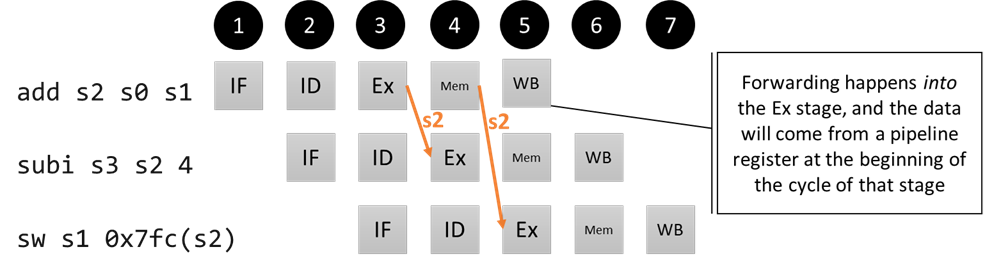
Why is the forwarding happening from the Mem/WB pipeline register in the second case? If we think about what needs to happen in terms of hardware, the signal needs to be made available in the same cycle it is used. By the time we reach the cycle where the sw address computation needs the data (beginning of Ex), the depending instruction is about to start the WB stage, so that’s where the data will come from. Concretely, the forwarded data comes from the pipeline registers (from Ex/Mem for the subi and from Mem/WB for the sw), since they are what holds the data for any given stage. We’ll talk about what it looks like to implement the forwarding unit logic in a bit, but for now, we’ll make a bunch of pipeline diagrams that will illustrate all of the cases that we’ll need to handle.
A preview of the forwarding wires
The same idea can carry through to an ALU operation that’s followed by a store. It’s simpler to just forward everything to the Ex stage, even though the store won’t use the value until the Mem stage.
Pipeline diagram for our Ex/Ex hazards including forwarding
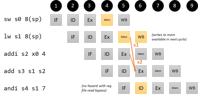
Mem/Ex hazards:
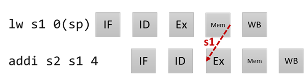
What about loads that introduce hazards in subsequent instructions? Consider the following example:
addi s0 x0 11
nop
nop
sw s0 8(sp)
lw s1 8(sp) # s1 = 11; no dependency; memory updates immediately in mem stage
addi s2 x0 4 # s2 = 4; no dependency
add s3 s1 s2 # s3 = 11 + 4 = 15; s1 dependency 2 instrs ago; s2 ex/ex dependency 1 instr ago
andi s4 s1 7 # s4 = 11 | 7 = 3; no dependency (with read bypass)
We’re purposefully avoiding an example where the dependency happens right after the load (where the addi instruction is now), because it turns out that case is a bit more complicated. We’ll come back to it in Step 4. If we take a look at the pipeline diagram, it turns out that we can forward from the lw instruction’s Mem/WB register into the add instruction’s Ex stage. Our hardware will either need to pass along the ALU result (in the case of an Ex/Ex dependency) or the load result (in the case of a Mem/Ex dependency) from the Mem/WB register if our forwarding unit detects a dependency. Notice also that the add instruction has two dependencies, one for each of its operand registers.
Pipeline diagram for our Mem/Ex hazard
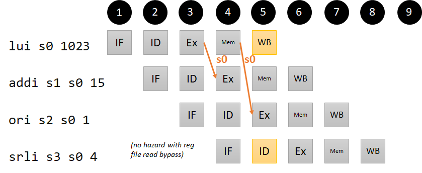
LUI hazard
Data hazards are introduced when an instruction needs data that hasn’t reached writeback yet. The data for a writeback to the destination register can come from four places: the ALU, data memory (in the case of a lw), the link register computation (PC+4), and the immediate (for LUI). We’ve considered the ALU and data memory in our examples above. We do not worry about an example where PC+4 needs to be written back to a register, because that only happens in the case of JAL and JALR, and the flush in Step 2 ensures that the values will be written back before any other instructions need these registers. For completeness, we include a code example for the lui instruction (it turns out that this won’t add much complexity to our forwarding logic, but it will help us check our work):
lui s0 1023 # s0 = 4190208 (0x003ff000)
addi s1 s0 15 # s1 = 4190223 (0x003ff00f); s0 dependency 1 instruction ago
ori s2 s0 1 # s2 = 4190209 (0x003ff001); s0 dependency 2 instructions ago
srli s3 s0 4 # s3 = 261888 (0x0003ff00); no dependency (with read bypass)
Pipeline diagram for our LUI hazard
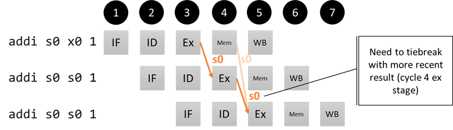
Consecutive Ex/Ex/Ex hazards
In the Ex/Ex hazard case, we saw that the dependency can come from 1 instruction ago, or from 2 instructions ago. What if the dependency is on the same register? For example:
addi s0 x0 1
addi s0 s0 1
addi s0 s0 1
In this case, we need the third instruction to see the latest value of s0, so our forwarding unit needs to prioritize which value it forwards (when the third instruction reaches the Ex stage, it should be getting the forwarded value of s0 from the Ex/Mem pipeline register, not the Mem/WB register, to accomplish this).
Pipeline diagram for our Ex/Ex/Ex hazard
Implementing the forwarding unit
Now that we have examples of the dependencies we can resolve by forwarding, let’s implement the forwarding unit. In a nutshell, we’ll need to compare the rd address in the Ex/Mem and Mem/WB pipeline registers (where the computation result is available) and compare it to the rs addresses in the ID/Ex pipeline register (right before the dependent instruction needs the data). Remember that the register file takes care to enforce that x0 is a read-only register, so we need to make sure we are not forwarding any values that would be “written” to x0.
First, we start with forwarding an ALU result which is needed in the subsequent ALU cycle (Ex/Ex dependency from 1 instruction ago). We also have to account for the LUI dependency from 1 instruction ago:
if (idex.rs[1/2]_id == exmem.rd_id) and
  (exmem.reg_wr) and
  (exmem.rd_id != 0):
    if (exmem.rd_sel == IMM):
        forward exmem.imm to rs[1/2] val in Ex stage
    else:
        forward exmem.alu_res rs[1/2] val in Ex stage
Next, we need to forward an ALU or Mem result which is needed two cycles later by the ALU (Ex/Ex dependency from 2 instructions ago, or Mem/Ex dependency from 2 instructions ago, or LUI dependency from 2 instructions ago):
if (idex.rs[1/2]_id == memwb.rd_id) and
  (memwb.reg_wr) and
  (memwb.rd_id != 0):
    forward RdSel output to rs[1/2] val in Ex stage
We are forwarding the RdSel output instead of the individual signals from the Mem/WB pipeline register because we assume multiplexers (such as the RdSel mux) are fast, and it means we only have to forward one output instead deciding between the ALU/load result/immediate.
We remember that we prioritize the latest result in the case of consecutive Ex/Ex/Ex hazards, so the first piece of logic (single-cycle dependency) takes precedence over the second piece of logic (two-cycle dependency).
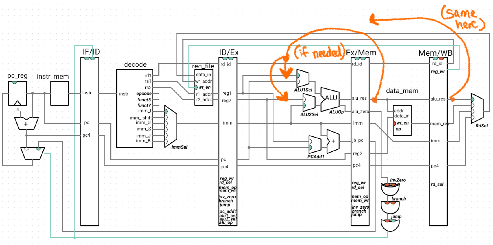
The forwarded result will be used by the ALU (input 1 in the case of rs1 and input 2 in the case of rs2). rs1 needs to be forwarded to the PCAdd1 mux, and rs2 needs to be forwarded to the reg2 input of exmem (this will take care of an ALU result that needs to be forwarded to the data of a store, as we saw in the second Ex/Ex diagram). As we’ll see in the wiring below, we can simply implement the forwarding for each of rs1 and rs2 as a multiplexer that selects between the forwarding data (or current value of the registers, if no forwarding is necessary).
These expressions show that our forwarding unit needs to take in the following inputs:
- idex.rs[1/2]_id (also needs to be added to the idex pipeline register)
- exmem.rd_id
- exmem.reg_wr
- exmem.rd_sel
- memwb.rd_id
- memwb.reg_wr
In hardware, the if/else expressions would be translated to mutually-exclusive boolean logic that computes multiplexer inputs. The actual forwarding is done using two multiplexers, one for rs1 and the other for rs2. They select between:
- The non-forwarded value (ID/Ex register reg1/reg2)
- The ALU result from the Ex/Mem register
- The immediate from the Ex/Mem register
- The output of the RdSel mux (to select between the ALU result, load result, and immediate after the Mem/WB register)
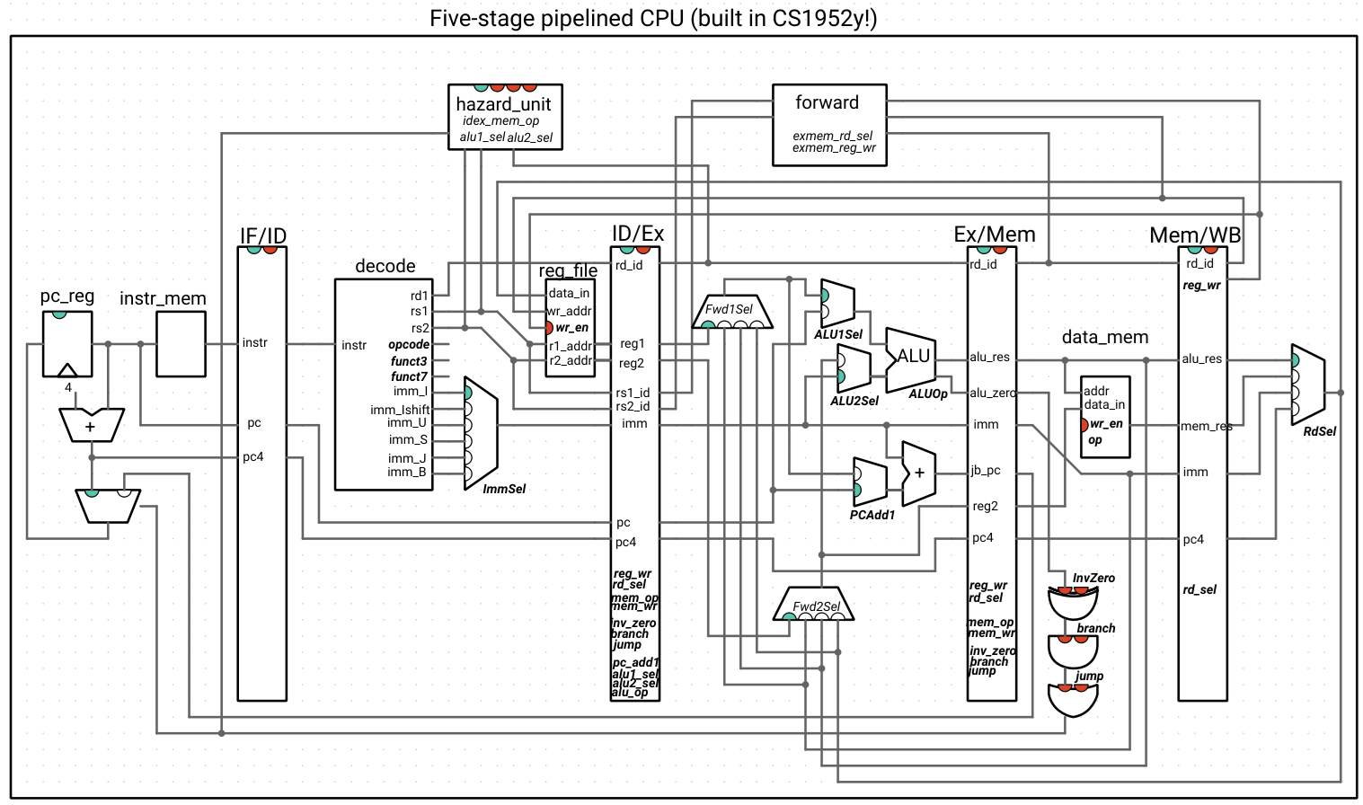
The output of these multiplexers replaces the inputs to the circuitry that took in the reg1/reg2 values in the Ex stage. Here is our CPU, with the forwarding unit:
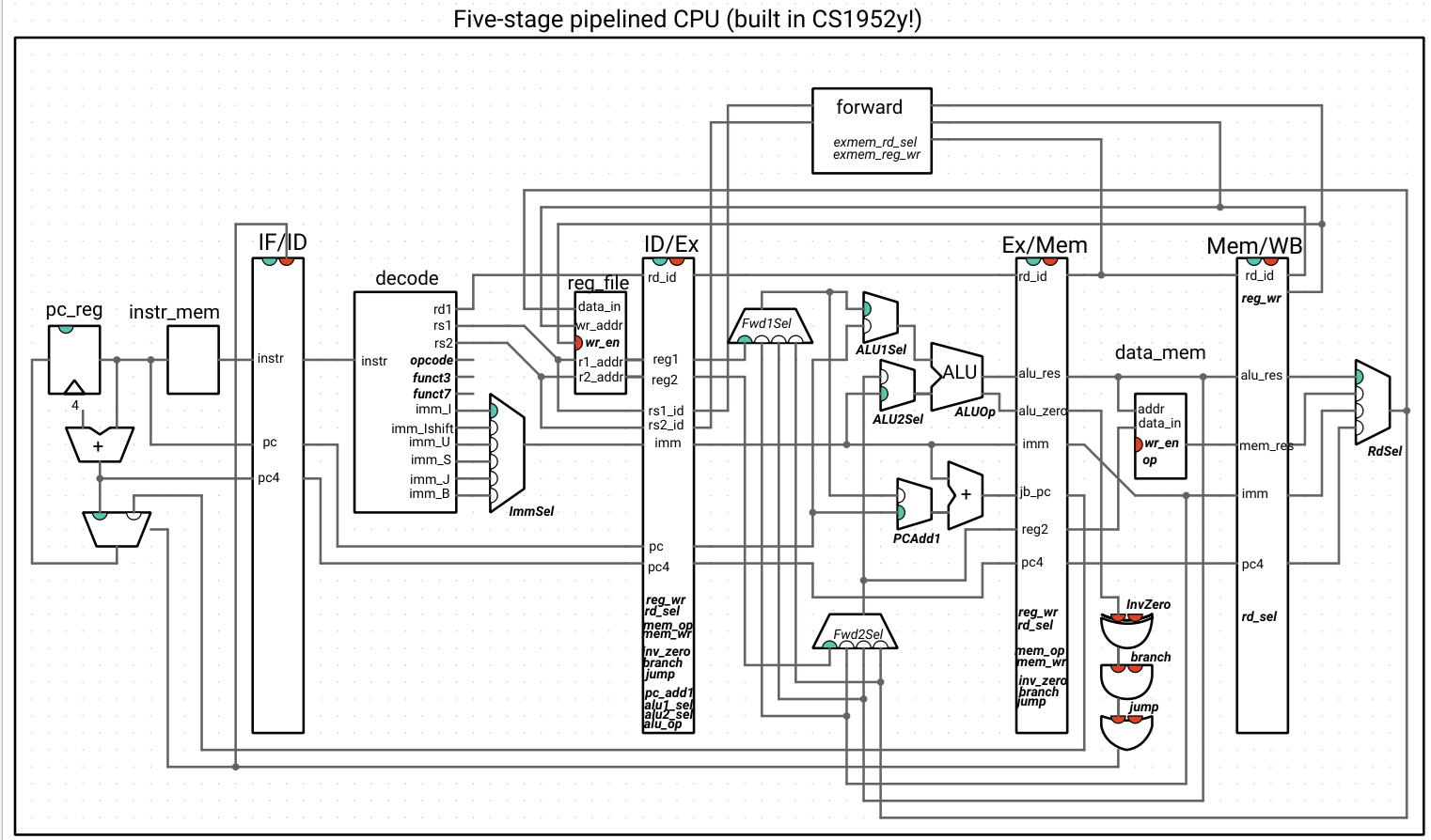
Note that the outputs of the forwarding unit are not indicated as wires and are the selection signals for the new muxes: Fwd1Sel and Fwd2Sel. The italicized names inside of the forwarding unit are the signals from the ExMem register that we haven’t drawn the wires for. All other wires connected to the forwarding unit are inputs.
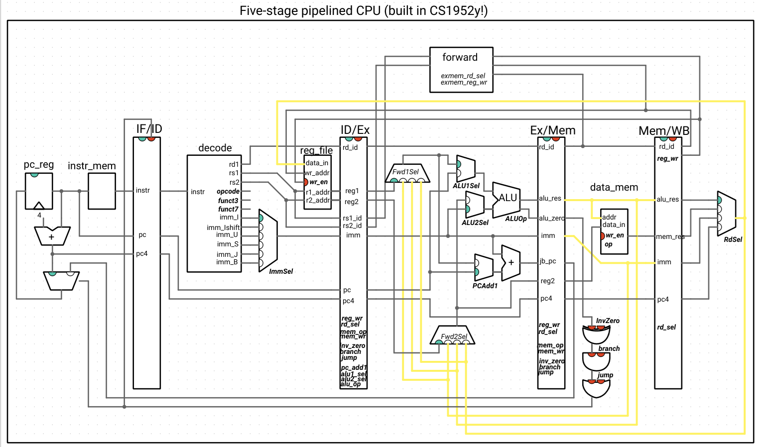
This may look like a distressing quantity of wires, so we highlight the wires that forward data to show that, alongside that logic, the new additions are the two multiplexers and the forwarding unit, with everything else staying the same:
If we try out our hazardous code examples, we see that they work correctly now.
Step 4: Resolving the last data hazard by stalling
There is one data dependency that cannot be solved using forwarding:
addi s0 x0 11
sw s0 0(sp) # resolved by forwarding
lw s1 0(sp) # s1 = 11; no dependency; memory updates immediately in mem stage
addi s2 s1 4 # s2 = 11 + 4 = 15; s1 dependency 1 instruction ago
This is because the lw instruction is in the Mem stage when the addi instruction is in the Ex stage, so the load result is not ready. We can’t forward backwards in time!
But something strange happens when we run this code on our 5-stage processor with forwarding – can you explain what is going on, based on our forwarding logic?
Remember our logic for forwarding an ExEx hazard? When we wrote this code, we weren't thinking about Mem/Ex hazards with 1 cycle between them, so the first part of the logic evaluates as What happened?
if (idex.rs[1/2]_id == exmem.rd_id) and
  (exmem.reg_wr) and
  (exmem.rd_id != 0):
    if (exmem.rd_sel == IMM):
        forward exmem.imm to ALU[1/2]Sel input 1
    else:
        forward exmem.alu_res to ALU[1/2]Sel input 1
(s1 == s1) and true and true (i.e. true), and the forwarding unit tries to forward the ALU result (the address computation) from the load instruction to register s1 when the hazard is detected (one cycle earlier than the memory operation). Obviously, this is a nonsense result and not desirable, but we'll see how the actual solution helps us use our forwarding unit as-is to avoid this.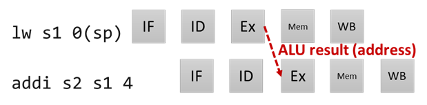
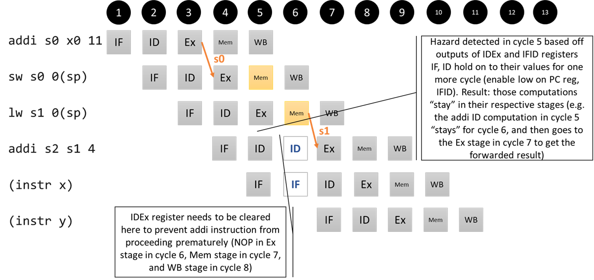
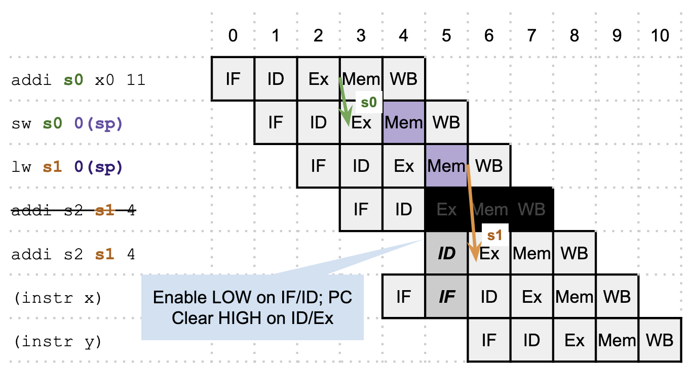
What if we could force a delay between the lw and the addi, so that this becomes like the regular Mem/Ex hazard we know how to deal with? We can, by detecting the hazard when the addi is in the ID stage. Before it’s supposed to go to the Ex stage, we can clear the ID/Ex register (effectively turning the rest of the instruction into a NOP) and disable the IF/ID register (remember, this just means that the register holds on to its old value for one more cycle), so that the instruction “repeats” its ID stage in the next cycle and is effectively delayed. We need the clear to ensure that the “first pass” of the instruction doesn’t run to completion. We also need to keep in mind that whatever instruction is after the addi is already in flight (in the IF stage) at this point, so we also need to disable the PC register so that that instruction can repeat its IF stage (otherwise, the PC will get incremented but IF computation will get lost because the IF/ID register is disabled). Once the stall completes, our forwarding unit (as written!) can forward the register for us.
An alternative way to draw the same operation, with the effects of the ID/Ex clear shown explicitly:Pipeline diagram for our Mem/Ex hazard that requires stalling
A hazard unit in the ID stage is able to detect this:
if (decode.rs[1/2]_id == idex.rd_id) and
  (decode.alu[1/2]_sel == reg) and
  (idex.rd_id != 0) and
  (idex.mem_op == [load operation]):
    stall
The (decode.alu[1/2]_sel == reg) condition checks to see that the source register in question is actually being used – since those bits are passed around regardless of the type of instruction, sometimes they may be part of an immediate field and still match rd, and we do not want to stall in that case. We did not need this clause in the forwarding unit, because the alu[1/2] selection multiplexers came after the forwarding multiplexers and took care of routing the correct data for us.
A note on the code: because the PC and IF/ID registers will never have enable driven low independently, the hazard unit in the code produces a single signal, if_enable, which we tie to both registers in cs1952y5s_cpu.h with the lines hazard_unit->if_enable >> pc_reg->enable; and hazard_unit->if_enable >> ifid_reg->enable;.
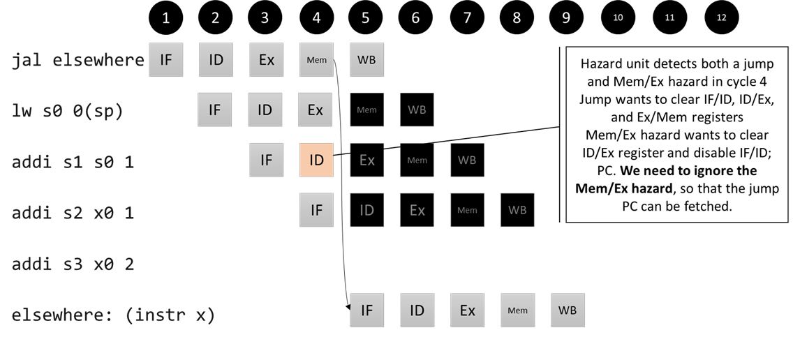
We also incorporate the flushing logic from step 2 into our hazard unit (see src/processors/CS1952y/five_stage_cpu/step4/cs1952y5s_hazard.h). Not only does this put all the pipeline stall/flush logic in one place, it allows us to handle a subtle but important interplay between data and control hazards. When a jump or branch happens, we shouldn’t drive the enable signals low, even if a data hazard is being detected in the ID stage, because the fetch stage will have the correct logic to fetch the instruction when the branch/jump reaches the mem stage.
Interaction of control hazard (flush) and data hazard (stall)
Again, we have three control signals that come from the pipeline registers that we list inside the hazard unit box. The other inputs are connected to the unit. The indicators at the top duplicate the indicators on the pipeline registers (enable for PC/IFID, clear for IFID, clear for IDEx, and clear for ExMem). Normal (non-hazard) operation is when the first indicator (PC/IFID enable) is high/green and the rest (the clear signals) are low/red.
Now our CPU works correctly and performs fairly well! While this is the design discussed in P&H, there’s no law saying we have to split every CPU into five stages – your homework will explore a design with four stages and with six stages.
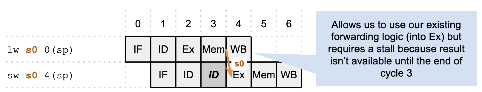
Note: missing lw/sw hazard
A student in the class pointed out that this processor doesn’t handle one specific hazard:
lw s0, 0(sp)
sw s0 4(sp)
As written, our hazard unit doesn’t detect a hazard here. We have two options:
First option (stall)
Second option (new forwarding logic)
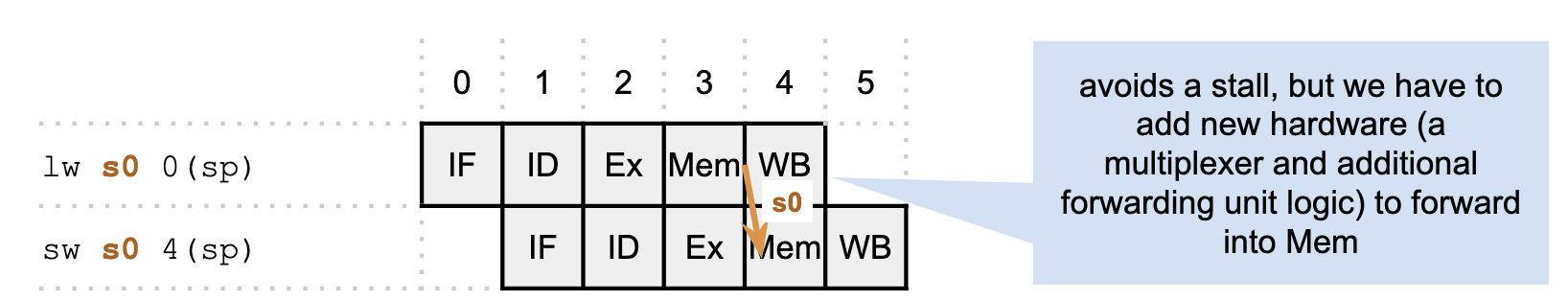
The textbook recommends the second option:
Forwarding can also help with hazards when store instructions are dependent on other instructions. Since they use just one data value during the MEM stage, forwarding is easy. However, consider loads immediately followed by stores, useful when performing memory-to-memory copies in the RISC-V architecture. Since copies are frequent, we need to add more forwarding hardware to make them run faster. If we were to redraw Figure 4.51, replacing the sub and and instructions with ld and sd, we would see that it is possible to avoid a stall, since the data exist in the MEM/WB register of a load instruction in time for its use in the MEM stage of a store instruction. We would need to add forwarding into the memory access stage for this option. We leave this modification as an exercise to the reader.
These notes will be updated next year (Spring 2027) to incorporate this.