Homework 1
This homework will be released in six parts. Part a is setup, part b has a conceptual component, and parts c-e will each have a small code component and a small conceptual component. The goal of the homework is to review low-level hardware and programming concepts and to build a foundation for future assignments. When you submit your work, you will be able to see your results so that you have immediate feedback. You can resubmit as many times as you want. This setup is different from the rest of the assignments in the course, because the role of this homework is different than the roles of the remaining homeworks, which will challenge you more on critical thinking and engaging with novel concepts.
Note about due dates: the “soft” due date for each homework is the next day of class. To accommodate people finding the class late during shopping period, the homework will not actually be counted late until the “hard” due date, which is Friday, February 7.
Homework 1a: Setup
Complete the development setup. There is nothing to submit for this part, but please get it done by Monday, Jan 27 so that you can troubleshoot if needed. Homeworks 1c, 1d, and 1f will ask you to run Ripes, and Homework 1e will ask you to modify and rebuild Ripes.
Homework 1b: Data representations
Soft due date: Mon, 1/27
This assignment reviews data representations (binary and hexadecimal, twos-complement, sign-extension).
Homework 1c: RISC-V assembly
Soft due date: Wed, 1/31
This assignment introduces working with RISC-V assembly and practices some of the data representation concepts from the previous assignment.
See resources page for RISC-V resources, including a copy of P&H fig. 2.1. For referencing the RISC-V spec, note that we are working with the 32I instruction set for this homework.
Conceptual component (for this and the remaining parts of HW1, we recommend doing the conceptual component first, because it may provide insights on how to approach the coding component)
Coding component: Write RISC-V code that:
- Places the value
0xdecafbadin register a3/x13 using the instructions listed in P&H fig. 2.1 only (no pseudoinstructions). Hint:0xdecafbadtakes up 32 bits, and no single RISC-V instruction fits a 32-bit immediate value. It’s up to you to find a combination of instructions that will do this. Pay attention to instructions that sign-extend immediates! - Negates the value from register a0/x10 in 2s complement and store the result in register a1/x11. Your answer should use the instructions listed in P&H fig. 2.1 only and cannot use the SUB instruction. Note: your code shouldn’t modify the value of register a0/x10.
Testing your code in Ripes
Note: this assumes you have completed the setup in HW1a. If you are still troubleshooting the setup, you may be able to use their experimental online version or another online RISC-V simulator to test your code instead. Note that you will be modifying and rebuilding Ripes in the next homework, so come to us for setup help if you need it!
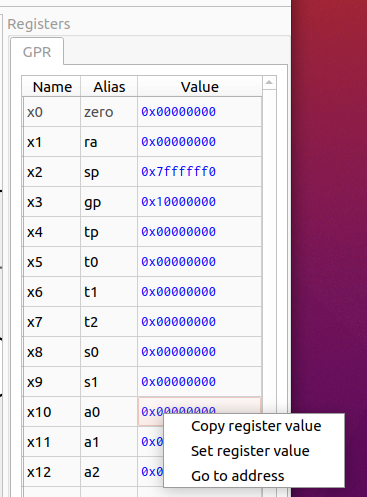
Ripes is a simulator that allows us to define an abstraction of a hardware circuit of a CPU and simulate how RISC-V code gets executed on that CPU (including observing how registers and memory change). In HW1d, we will be modifying Ripes. For now, we can use one of the processors that comes with Ripes to run RISC-V code. See here for the tutorial on how to interact with Ripes. For this homework, you should select the 32 bit single cycle processor. You can manually edit the value of the a0 register (see below) and step through your code to see that the correct operations are being performed:
Submit your code as a single .s file in the Gradescope assignment.
Homework 1d: Hardware and RTL
Soft due date: Fri, 1/31
This assignment provides an overview of the hardware concepts we need to understand how the simulators we work with would translate to real-world computers. It introduces logic gates, multiplexers, clocks and clocked registers, and register transfer level descriptions of circuits.
Your textbook describes some Hardware Description Languages (HDLs) that use code to describe a circuit at the Register Transfer Level (RTL). As your book describes, HDLs are used as inputs to synthesis tools that can generate hardware circuits, such as on Field-Programmable Gate Arrays (FPGAs). While we won’t be programming in Verilog/VHDL for this course, we will be using a specific C++ library (VSRTL) to describe and visualize hardware at the RTL so that we can simulate a processor. Contrasted with procedural-style programming, we are not writing algorithms. Instead, our code will be describing a logical function from input(s) to output(s), which is how hardware circuits work. A good example of VSRTL in action is their adder. Notice how the output port, out, is defined as a function that returns an answer based on the values of the two input ports.
In homework 2, our components will broadly have two tasks – extraction/translation and control. Extraction/translation circuits will extract specific bits from the input and possibly transform them (for example, extract the 20-bit immediate field from a RISC-V instruction and sign-extend it to 32 bits). Control circuits will set control outputs based on inputs (for example, set a 1-bit “memory write enable” control signal if inputs that correspond to the opcode and func fields of an instruction indicate a store instruction). In hardware, these circuits are implemented using a combination of routing different wires (which carry the signals for different bits) to different parts of the circuit and combinational logic.
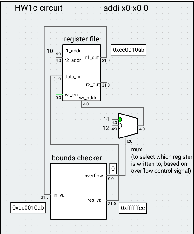
Your task is to implement a VSRTL component that with extraction/translation and control tasks. The component takes a single 32-bit input where bits [7:0] are a lower bound, bits [15:8] are an upper bound, and bits [31:24] are the test value (bits [23:16] are ignored). The upper/lower bound and test value are treated as signed, 8-bit integers. The component has two outputs: a 32-bit result value, and a 1-bit overflow control signal. If the test value is between the lower bound and upper bound (inclusive), the result value output should be the sign-extended test value and the overflow control signal should be 0. If the test value is lower/higher than the lower/upper bound, the result value output should be the corresponding violated bound (sign-extended) and the overflow control signal should be 1. Assume the inputs are well-formed, that is, that the lower bound is always less than or equal to the upper bound.
Example: For the input 0xcc0010ab, the lower bound is 0xab (-86), the upper bound is 0x10 (16), and the test value is 0xcc (-52), so the result value would be 0xffffffcc and the overflow control signal would be 0. If the input is 0x66ff5544, the result value would be 0x00000055 and the overflow control signal would be 1.
git pull the Ripes repo and edit the src/processors/CS1952y/HW1d/boundscheck.h file to implement this component. The input and outputs have been defined for you, so all you have to do is define the functions that compute the outputs based on the input (replace the expressions on lines 16 and 20 with your own code). Hint: since the two outputs are controlled by standalone functions, you will probably have repeated code for each. We’re not grading on style, so this is fine, but you can define helper functions if you want to cut down on this. You can implement sign-extension using casting in C++: casting a smaller int (such as int8_t) to a larger one sign-extends it (uints get 0-extended). To test your code, you can build Ripes by running make (with an optional -j4 or -j8 flag to speed up the build) in the top-level Ripes directory, and then run the command ./Ripes to run Ripes. Use the processor selection button at the top-right to open the HW1d Circuit “processor.” The bounds check component’s input is attached to register a0 in this circuit, so you can set the value of the register, run any instruction (we like nop, which does nothing) for one cycle, and view the output of the component. Note that this just a bare-bones circuit meant to show the functionality of the bounds checker, and not a processor implementation, so you cannot run RISC-V code using it. The circuit is designed to write the result to register x11 or x12 based on the overflow signal, primarily for autograder reasons.
Submit the boundscheck.h file to Gradescope.
Homework 1e: Memory operations
Soft due date: Mon, 2/3
In preparation for implementing memory operations on our CPU, this assignment has you work with memory operations in RISC-V assembly, including memory on word-/half- boundaries. Review section 2.6 of the RISC-V spec, especially the descriptions of word, half-word, and byte loads and stores on page 19.
Translate the c code f = A[B[g + 2]] into RISC-V assembly using lw and arithmetic instructions. Assume the code will run without error (that is, all indices will be in-bounds). Assume A and B are arrays of unsigned, 32-bit integers, and assume g is stored in register a0/x10 and f is stored in register a1/x11. Use the following starter code, which gives you the addresses A and B (note: our autograder requires that the first six lines of the code you turn in are exactly as follows – don’t add comments to or before these lines!):
.data
A: .word 0x20000000
B: .word 0x20000020
.text
lw a2, A
lw a3, B
To test your code, you might want to use the sw command. For example, to store the value of register a4 into B[0], you would write lw, a3, B to put the address referred to by B in a3, and then write sw a4, 0(a3) to store the value. Make sure to remove your store commands for the code you turn in, or you might not pass our tests!
Now, repeat the task, but use lh/lhu in place of lw (lines 5-6 of the file, as given, should still use lw). f, and g should still be interpreted as 32-bit integers (and A and B as arrays of unsigned, 32-bit integers).
Submit your code as word.s and half.s, respectively.
Homework 1f: Design tradeoffs and analysis
Due date: Fri, 2/7
So far in class, we have been focusing on getting a working CPU, instead of worrying about efficiency. This homework starts to explore various tradeoffs between space, speed, and power. We also practice jumps and branches in RISC-V and get a preview of ISA extension design!
Conceptual component: For this assignment, we suggest trying the code component first, to get familiarity with the multiplication algorithm.
The RISC-V 32I base instruction set doesn’t have a multiplication instruction. We have two options: use the M extension, or implement multiplication in software. The conceptual part of the homework gives you some examples of what the hardware might look like when implementing the M extension. For the coding part of the homework, let’s practice using control transfer instructions in RISC-V and implement multiplication.
A naive algorithm for multiplying two numbers A and B might be:
P = 0;
while (B > 0) {
    P += A;
	B--;
}
return P;
The problem with this algorithm is that the runtime scales linearly with the multiplier B. An alternative approach for unsigned numbers, called “shift and add,” is inspired by long multiplication and takes 32 iterations (or however many bits our operands have). The pseudocode is given below:
P = 0
for 32 times:
    if LSB of B is 1:
        P += A
    shift B right 1
    shift A left 1
Note that the result of multiplying two 32-bit numbers together might be 64 bits long. Don’t worry about this for this homework – if P is in a 32-bit register, this algorithm will produce the 32 lower bits of the answer. Assuming A (the multiplicand) is in x10, B (the multiplier) is in x11, and P (the product) should be stored in x12, implement the shift and add algorithm in RISC-V. Your implementation does not have to save the values in x10 and x11. Try running your code with various inputs and observe the number of cycles each program takes to complete – it should not vary very much with input size (this information can be found in the statistics pane of the processor tab of Ripes). Note: it is possible to make this algorithm run faster for small numbers by stopping when B becomes 0. Because the conceptual homework looks at this implementation from a hardware perspective (where clock speeds are computed to accommodate the worst-case time that a circuit takes to stabilize), we’re asking you to run the loop 32 times.