Building a single-cycle CPU in Ripes (Part 2 -- more instructions that write to registers)
Previously: Single-cycle CPU part 1; Next: Single-cycle CPU part 3
Step 2: Adding support for the Register-Register instructions
These instructions provide two input register addresses, two function fields, and write the output to the destination register. They are R-type instructions:
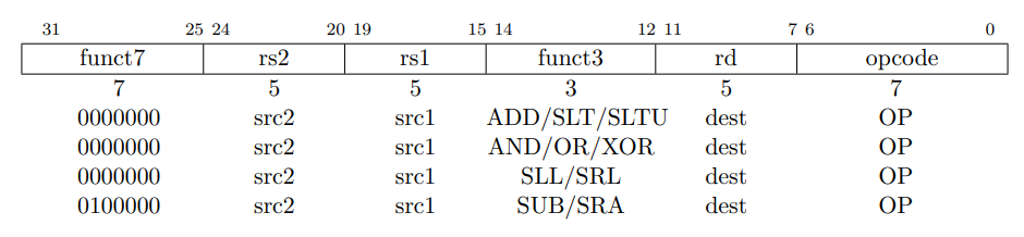
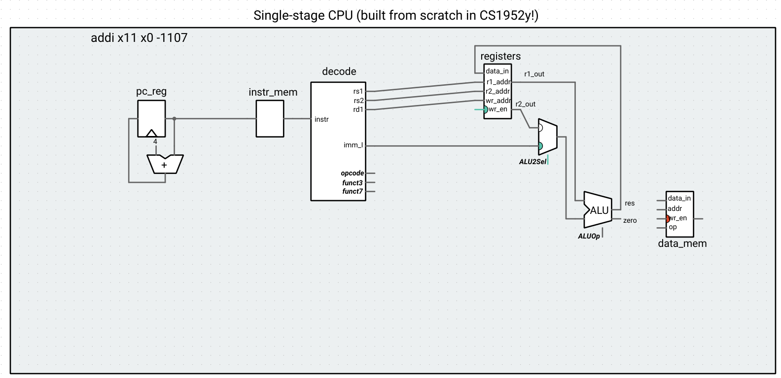
While the lower 20 bits are used for the same purpose as the I-type instructions we looked at earlier, the upper 12 bits serve a different purpose. For the I-type instructions, the immediate field went into the op2 input for the ALU. For the R-type instructions, we have to read the value of the rs2 register and then use it as an input to the ALU. This doesn’t mean we have to use two different ALUs for these two different types of instructions! For both instructions, one input to the ALU will be the value of rs1. The other will either be the value of rs2 or the immediate. We can introduce a mux right before this second input, where our selection signal is based on what instruction type we’re dealing with (based on the opcode of the instruction).
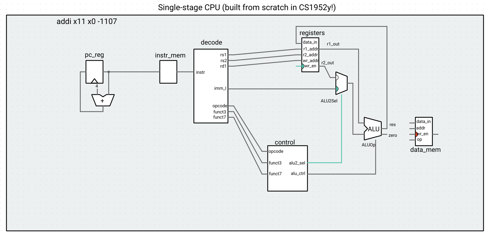
Instead of making our translator do all the work, it’s a big more ergonomic to split it into two parts:
- The decode unit splits up the instruction into named bit fields and puzzles together and sign-extends any immediate(s). In hardware, this would simply be done with wires, but we encompass it in its own component to draw some abstraction boundaries in our diagram.
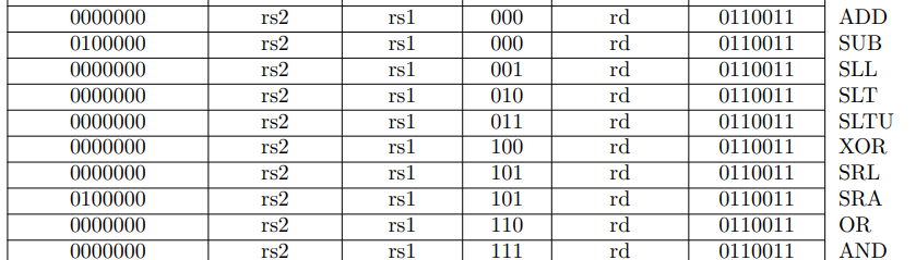
- The control unit takes in the values of the opcode/funct field(s) and outputs control signals to the subsequent components of the CPU, such as the control signal of the ALU and the selection bits to any multiplexed data. In hardware, this would be done using logic gates that essentially create a lookup/translation table. Notice the clever design of the funct3 fields of the two types of instructions – for example, 100 is the funct3 field for XOR and for XORI. This is not a coincidence – since the same ALU control signal is used for both instructions, this enables less hardware to be used when creating the control unit in real life.
Controlling the selection signal for the ALU2Sel mux in cs1952y1s_control.h
    alu2_sel << [=] {
      switch (opcode.uValue()) {
      case 0b0010011: // I-type
        return ALU2Sel::IMM;
      case 0b0110011: // R-type
        return ALU2Sel::REG2;
      default:
        return ALU2Sel::IMM;
      }
The decode unit is agnostic to the type of operation – it will always output something for imm as if the instruction were I-type, and something for rs2 as if the instruction were R-type. Of course, if the instruction is not of those types, the data in those outputs is essentially garbage. That is why we need the control unit, to make sure that only the well-formed data is routed to the other components using muxes.
Our CPU can now handle two types of instructions!
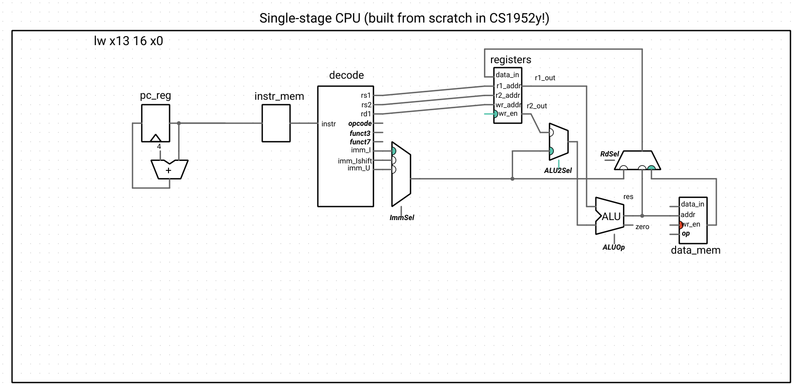
Our control unit will become very complicated as we implement the rest of the instructions! For legibility, we have hidden the control unit and indicated the signals that are connected to control inputs/outputs using bold and italicized text. Just keep in mind that the control unit still exists and takes in the opcode/func field(s) output by the decode unit as inputs and produces all of the subsequent control signals as outputs.
Step 3: Adding support for the remaining Register-Immediate instructions
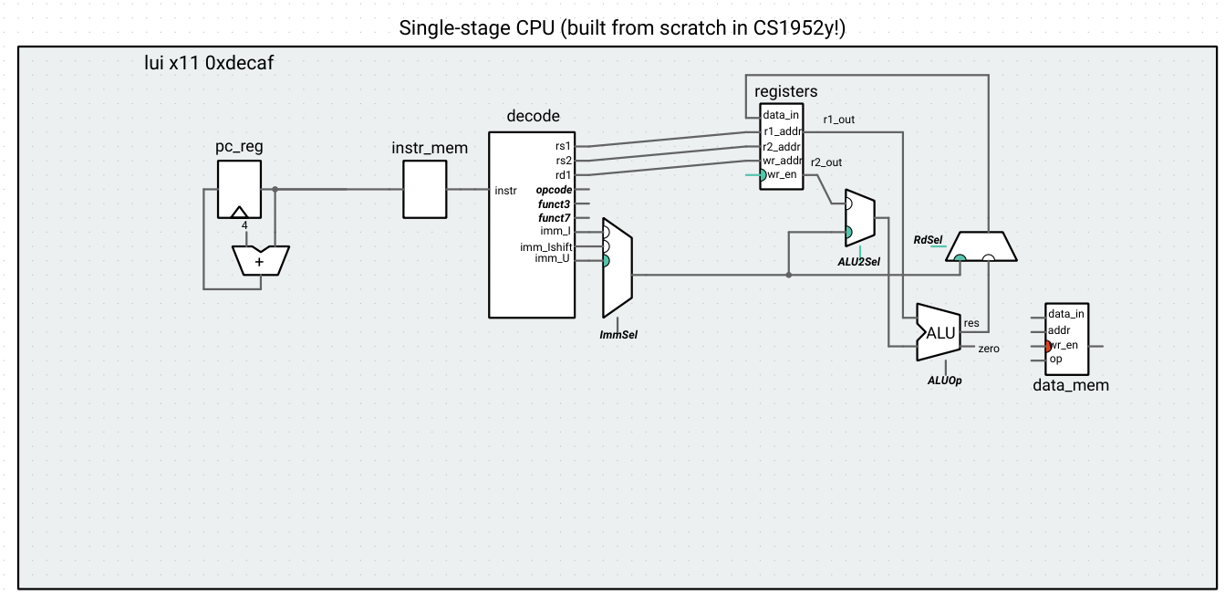
Understanding the principle of the control unit, we can now implement shifts with immediates, as well as LUI.
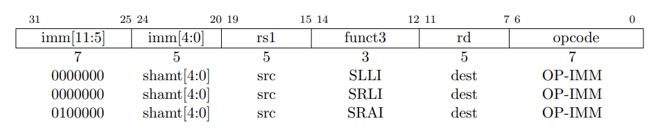
In terms of decoding, the shift operations are a special case of the I-type instruction, where the upper 7 bits of the immediate field act more like a funct7 field (a fact which we take advantage of when implementing the control unit). Since an instruction has at most one immediate, we introduce an immediate selection mux, so that the control unit can route the correct type and size of immediate based on the type of instruction.

Updated logic for alu_ctrl to support shift-immediates
if (opcode.uValue() == 0b0010011) { // I-type
    switch (funct3.uValue()) {
    ...
    case 0b001: // SLL
        return ALUOp::SL;
    ...
    case 0b101: // SRLI and SRAI
        if (funct7.uValue() == 0) {
            return ALUOp::SRL;
        } else if (funct7.uValue() == 0b0100000) {
            return ALUOp::SRA;
        } else {
            throw std::runtime_error("Invalid upper 7 bits for SRLI/SRAI");
        }
    ...
LUI does not make use of the ALU, but instead writes data to a register. We introduce a multiplexer that selects between the immediate from this instruction and the ALU output when writing to the destination register.

Immediate selection and rd logic
    imm_sel << [=] {
      switch (opcode.uValue()) {
      case 0b0010011: // Register-immediate
        if (funct3.uValue() == 0b001 || funct3.uValue() == 0b101) { // shift
          return ImmSel::Ishift;
        } else {
          return ImmSel::I;
        }
      case 0b0110111: // LUI
        return ImmSel::U;
      default:
        return ImmSel::I;
      }
    }; // imm_sel

    rd_sel << [=] {
      switch (opcode.uValue()) {
      case 0b0110111: // LUI
        return RdSel::IMM;
      default:
        return RdSel::ALU;
      }
    }; // rd_sel
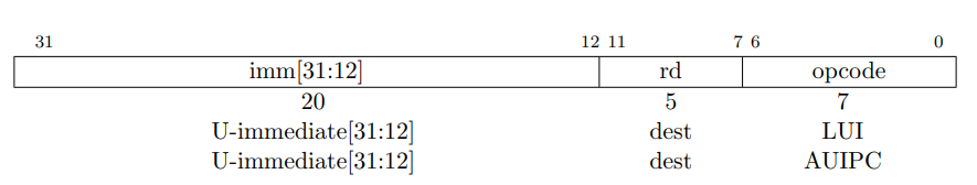
We must also pay attention to how the U-immediate is expanded into 32 bits when decoding a U-type instruction when implementing our decode unit.

Immediate decode
    // Immediates
    imm_I <<
        [=] { return instr.sValue() >> 20; }; // bits 20 to 31 (sign-extended)
    imm_Ishift <<
        [=] { return (instr.uValue() >> 20) & 0x001f; };  // bits 20 to 24
    imm_U << [=] { return instr.sValue() & 0xfffff000; }; // bits 12 to 31
Since AUIPC involves the PC, we’ll hold off on implementing control for this operation until we discuss jumps and branches.
You should now be able to run your code from HW1c on this CPU!
Step 4: Load instructions
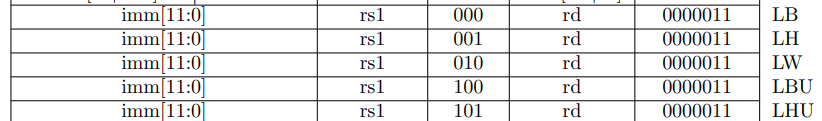
We can now easily implement LW, since the address computation is an I-type ADD instruction. There aren’t any new subcomponents to add, and we just have to make some connections to data memory and create a new input to the register data_in multiplexer. The memory controller itself does the sign-extend or 0-extend computation required for LB, LW, LBU, and LHU as long as we provide the correct control signal, so we get those operations for “free,” as well.
Updated CPU wiring
    // Data memory
    data_mem->mem->setMemory(m_memory);
    alu->res >> data_mem->addr;
    0 >> data_mem->data_in;
    0 >> data_mem->wr_en;
    control->mem_op >> data_mem->op;