Building a single-cycle CPU in Ripes (Part 1 -- I-type instructions)
Next: Single-cycle CPU part 2
Preliminary notes
Let’s construct our first basic CPU! “Single-cycle” means that every instruction will take a single clock cycle to complete. We’re not going to worry about how long this clock cycle is. We’ll just assume that it’s long enough to accommodate the longest path through the circuit between the time the PC incrementing and the instruction side effects being written to registers/memory.
RISC-V 32I ISA
We will be implementing the RISC-V 32I (32-bit integer) base instruction set. As always, the RISC-V specification can be found here.
Working with Ripes
We will build several CPUs using Ripes. Ripes gives us a lot of functionality, but we will mainly be doing two things: defining new components, and connecting components (that we have written or that exist in Ripes/VSRTL) to create a CPU. The easiest way to get caught up with the conventions of Ripes is to look at an example, such as the single stage processor they provide (we will be deviating from the provided design a bit, both to show that different implementations of the same ISA can exist, and because we will be building out our CPU incrementally).
When connecting components together to create a CPU, we need to define them as subcomponents (e.g. SUBCOMPONENT(alu, TYPE(ALU<XLEN>)); in rvss.h). We also need to make sure that every input of a subcomponent has been connected. The syntax for this is [wire source] >> [wire dest] (e.g. control->alu_ctrl >> alu->ctrl; in rvss.h). In hardware, this would look like putting electronic components onto a circuit and connecting the outputs of some components to the inputs of other components together with wires. We are just using VSRTL to describe this hardware for simulation.
When defining our own component, we need to define input and output ports (e.g. INPUTPORT(op1, W); in vsrtl_adder.h) and define how the outputs are set on each clock cycle. The syntax is [output] << [=] { [function to compute output] }; (e.g. out << [=] { return op1.sValue() + op2.sValue(); }; in vstrl_adder.h). We get the values of the input ports by using .uValue() or .sValue() (signed or unsigned values). The function to compute the output is run on every clock cycle.
Colorblind-accessible palettes
Unfortunately, VSRTL uses pure red (0xff0000) and pure green (0x00ff00) to represent on/off control signals. If you would like to change the colors of the indicators, you can do so by applying the provided patch (since most of the files that render the graphics are in the VSTRL submodule repo, this is the easiest way for us to provide this change). This patch changes instances of Qt::green to QColor{87,196,173} and Qt::red to QColor{219,67,37}, as per the recommendations here. Feel free to adapt the patch file to colors of your choosing.
# in the top-level Ripes repo:
patch -p0 < redgreen.patch
Coding along
The notes below give some example code snippets of relevant changes we make, but this page won’t include all of the code for each step. To access this code, go to the src/processors/CS1952y/single_stage_cpu directory in our course Ripes repo. The step0 subdirectory gives the code we end up with for step 0, and so on. The layouts directory gives the layout for every step (which you can select in the processor selection dialog to match the step we’re on). You will need to copy the code from a particular stepn subdirectory into the src/processors/CS1952y/single_stage_cpu directory and rebuild Ripes in order to run the partial processor from that step. To see what changes are made between steps, you can run your diff program of choice (Milda likes the Diff & Merge extension for VSCode).
Step 0: Incrementing the PC
We start with the bare-bones components we will need to implement our CPU: the register file, the instruction memory, the data memory, the ALU, and the PC register. An ALU takes in two operands and a control signal to select the operation to be done, and produces the result of that operation on the operands. We build on the rv_alu provided by Ripes by adding a “zero” signal, which is high when the ALU result is 0 and low otherwise. We will see why the zero output is helpful later on.
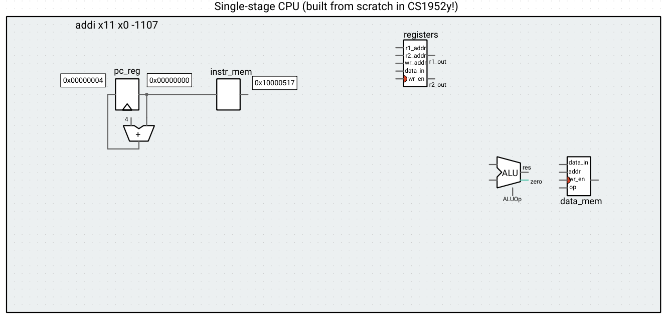
We’ll ignore most of these components for now and wire them up as we need them (to make sure the circuit runs in Ripes, we’ll just wire a 0 signal to the input of each one). Let’s first wire up a circuit to read an instruction from memory (using the current value of the PC as an address) and increment the PC by 4 at every clock cycle.
Part of cs1952y1s_cpu.h (wiring up the image seen below)
    // ** ADVANCING THE PC **
    pc_inc->out >> pc_reg->in;
    pc_reg->out >> pc_inc->op1;
    4 >> pc_inc->op2;

    // ** Instruction memory **
    instr_mem->setMemory(m_memory);
    pc_reg->out >> instr_mem->addr;

    // ** Registers **
    registers->setMemory(m_regMem);
    0 >> registers->r1_addr;
    0 >> registers->r2_addr;
    0 >> registers->wr_addr;
    0 >> registers->data_in;
    0 >> registers->wr_en;

    // ** ALU **
    0 >> alu->op1;
    0 >> alu->op2;
    ALUOp::NOP >> alu->ctrl;

    // Data memory
    data_mem->mem->setMemory(m_memory);
    0 >> data_mem->addr;
    0 >> data_mem->data_in;
    0 >> data_mem->wr_en;
    MemOp::NOP >> data_mem->op;
If we step through any RISC-V program, we see that the PC indeed gets incremented, and that the output of instruction memory is the corresponding instruction.
This is a great first step, because now we have a different instruction available to the CPU at each clock cycle, and we can start deciphering the bits therein. Instead of tackling all possible instructions at once, let’s go through the RISC-V spec piece-by-piece and figure out what we need for each instruction type.
Step 1: Adding support for Register-Immediate instructions
As we learned, these instructions provide an immediate value, an input register, and a function field, and write the output to the destination register. They are I-type instructions (for now we ignore LUI, AUIPC, and the shift operations):
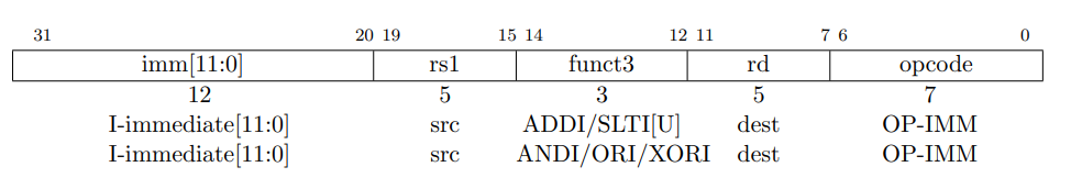
The OPCODE field has a special value (which we can look up later) that tells the CPU that this is an I-type instruction. For now, let’s assume that all instructions our CPU is running are I-type, so we can safely ignore it. The value in the funct3 field will tell us which instruction we’re dealing with.
Note that a NOP (no-op, or empty instruction) is a pseudoinstruction encoded as ADDI x0 x0 0. Since x0 is hardwired as the constant 0, it is a read-only register, and “writing” to it has no effect. Thus, as long as we implement ADDI correctly, NOP will work correctly, as well.
To provide support for this instruction, we need a translator that takes in the 32-bit instruction (the output of the instr_mem component) and:
- Extracts the immediate value, source register address, and destination register address
- Extracts and transforms the funct3 field of the instruction to the proper control signal of the ALU
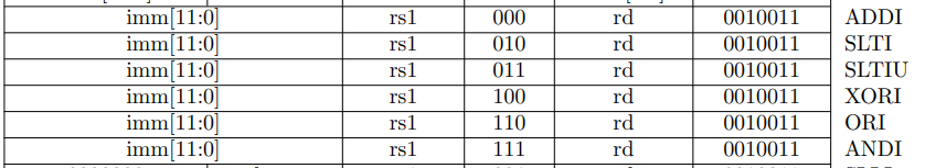
The first step is just a matter of selecting the correct bits according to the I-type instruction fields. For the second step, we need to know what bits of the funct3 field correspond to what operations, which we can find with the help of the table in chapter 19 of the RISC-V spec:
Translator bit extraction (cs1952y1s_translate.h)
    // Registers
    rs1 << [=] { return (instr.uValue() >> 15) & 0x001f; }; // bits 15 to 19
    rd1 << [=] { return (instr.uValue() >> 7) & 0x001f; };  // bits 7 to 11

    // Immediate
    imm <<
        [=] { return instr.sValue() >> 20; }; // bits 20 to 31 (sign-extended)
This translation would be done with a combinational logic circuit in hardware. Because we’re working with the assumption that modern hadrware synthesis tools can automatically generate these sorts of circuits from RTL, we define a switch statement to model it in our software simulator (if you’re interested in the actual mechanics, read Appendix C of P&H!).
funct3 switch statement
// ALU control signal
alu_ctrl << [=] {
    auto funct3 = (instr.uValue() >> 12) & 0x0007; // bits 12 to 14
    switch (funct3) {
    case 0b000: // ADDI
        return ALUOp::ADD;
    case 0b010: // SLTI
        return ALUOp::LT;
    case 0b011: // SLTIU
        return ALUOp::LTU;
    case 0b100: // XORI
        return ALUOp::XOR;
    case 0b110: // ORI
        return ALUOp::OR;
    case 0b111: // ANDI
        return ALUOp::AND;
    default:
        throw std::runtime_error("Invalid funct3 field");
    }
};
Once we define the translator, we make the appropriate connections to the ALU and the register file.
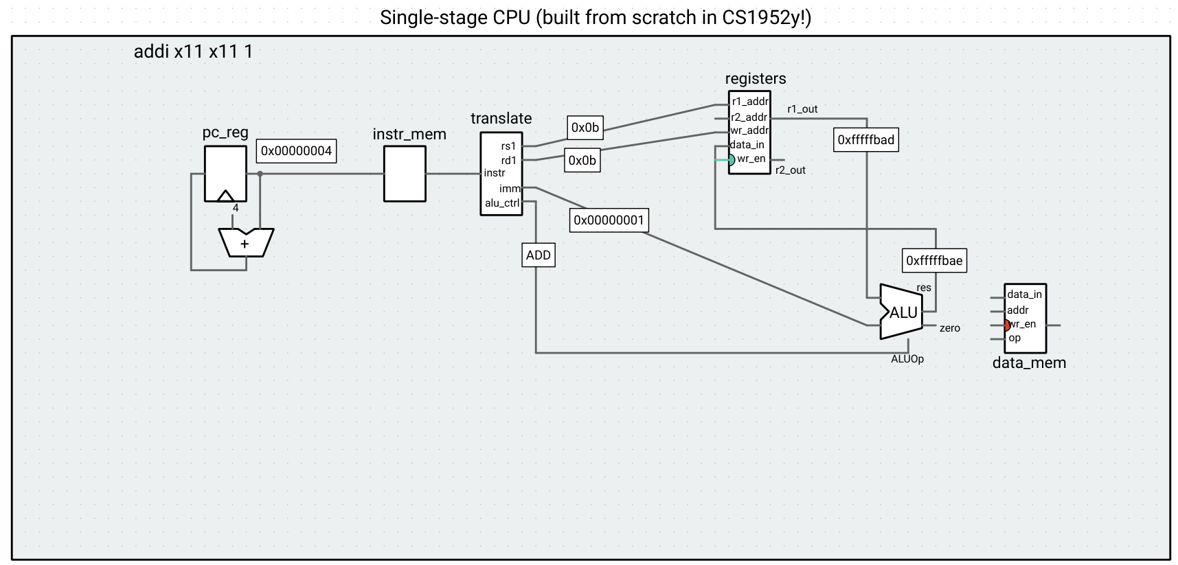
We can run some I-type instructions through this CPU (for example, addi x11, x0, 0xbad,
addi x11, x11, 1), and observe that the computations indeed get performed. Note the result of the writeback to the register file becomes available in the subsequent clock cycle to when the operation is run (we will revisit this design of the register file when we get to pipelining).
Next time, we will make our CPU implement more types of instructions.