Building a five-stage pipelined CPU in Ripes (Part 1 -- Setting up)
Previously: Single-cycle CPU part 3; Next: Pipelined CPU part 2
Intro
We will be working in the src/processors/CS1952y/five_stage_cpu directory. As for the single-stage notes, the code for the intermediate steps is given in the subdirectories.
Step 1: Adding pipeline registers

In a pipeline, the execution of an instruction is broken up into stages, so that multiple instructions can be “in flight” at the same time, all executing different stages. Our stages will follow the P&H breakdown of Instruction Fetch (IF), Instruction Decode (ID), Execute (Ex), Memory (Mem), and Writeback (WB). An instruction will now take five clock cycles to execute, one for each stage.
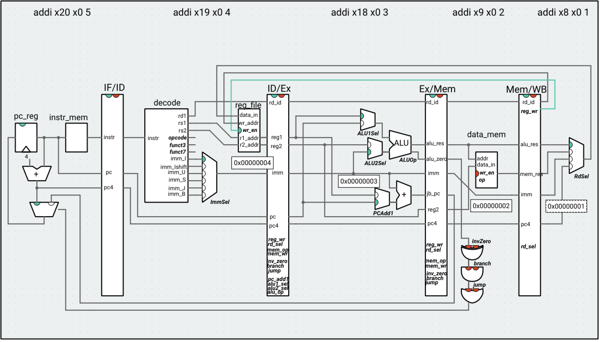
To marshal the correct data through the pipeline, we need to put registers between each of the stages. The registers will allow the processor to synchronize data on the clock signal – if an instruction is in the IF stage at clock cycle n, the register will hold on to that data until clock cycle n + 1 and pass it on to the ID stage, without stomping over the instruction that was in the ID stage in cycle n. Along with any computational data (register values, immediates, ALU results, memory loads), we will need to pass along any control signals that are needed for subsequent cycles. Here, we list the signals that each stage needs from the previous stages. In parentheses, we indicate the stage where the signal originated, meaning that we will need to pass that signal through any intermediate preceding stages, as well.
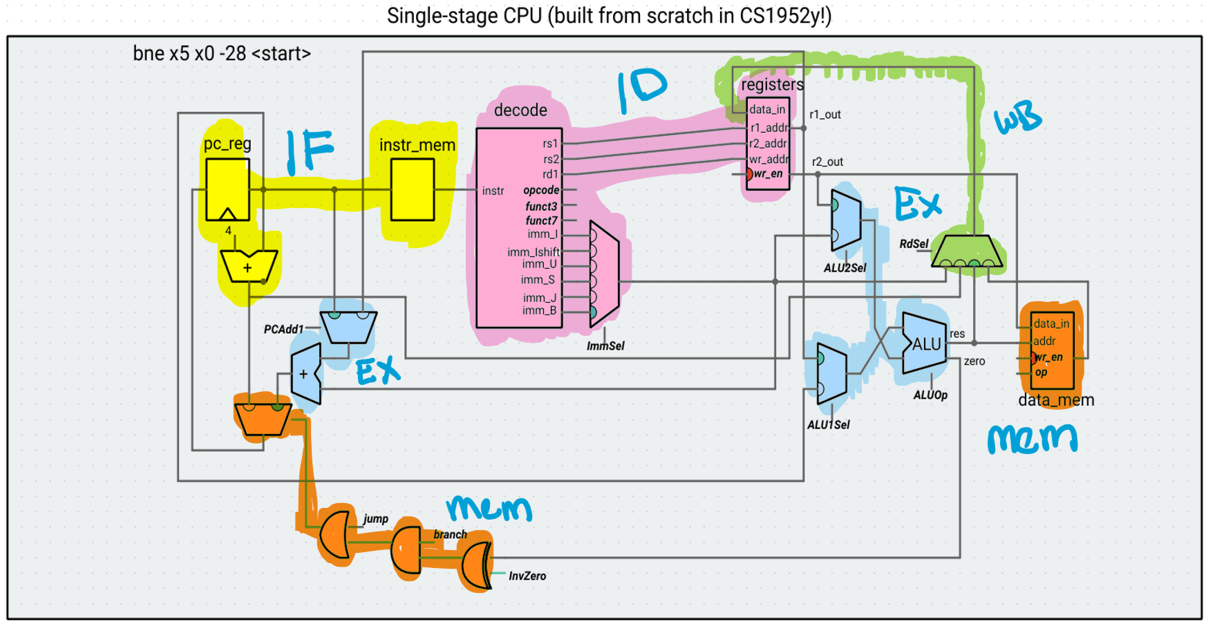
As you read through this list, pause and think to yourself about why a specific stage needs a specific piece of data (for example, the Ex stage needs the PC because the AUIPC instruction uses the ALU and because the new PC for jumps/branches will be computed in this stage). Another way to verify this is by looking at the diagram above. For example, the Mem stage needs the value of R2 because the data_mem component from that stage takes that data in as an input.
The ID stage needs:
- The instruction (IF)
The Ex stage needs:
- The PC (IF)
- The value of R1 (ID)
- The value of R2 (ID)
- The immediate (ID)
-
The control signals ALU1Sel, ALU2Sel, and ALUOp (ID)
This stage will hold the adder that computes the new PC for any jump/branch, using the old PC or R1 and the immediate, so it also neeeds:
- The control signal PCAdd1 (ID)
The Mem stage needs:
- The result of the ALU (Ex)
- The value of R2 (ID)
-
The control signals MemWr and MemOp (ID)
To route back to the mux that selects between PC+4 and any newly computed PC, this stage also needs:
- The result of the adder that computes the new PC (Ex)
- The zero signal of the ALU (Ex)
- The control signals jump, branch, and InvZero (ID)
The WB stage needs:
- The result of the ALU (Ex)
- The immediate (ID)
- The value of PC + 4 (IF)
- The result of the memory read (Mem)
- The ID of the Rd register (ID)
- The control signals RdSel and RegWr (ID)
For now, we are ignoring anything that messes with the pipeline due to in-flight instructions affecting the outcome of other in-flight instructions (data and control hazards). We still include the branching/jumping and writeback circuitry for when we address these hazards, but we cannot safely run writeback and control instructions that depend on instructions still in the pipeline.
As before, to reduce visual clutter, we omit control signal wires and use bolded and italicized text to indicate where the control signals are used. The exception is reg_wr, which we explicitly show as going “back” to the register file (because the write functionality of the register file occurs in the writeback stage). Any control signal used in a specific pipeline stage comes from the preceding register (for example, ALU1Sel comes from the ID/Ex register, while RdSel comes from the Mem/WB register).

Ripes tricks for pipelines
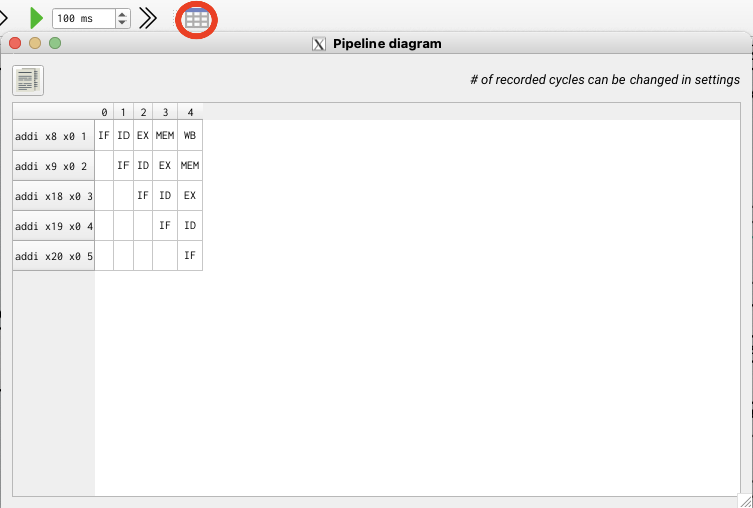
You can click the “show pipeline diagram” button in Ripes to see which instructions were in which stages for each cycle. Time moves right to left, and each stage will be in use at most once in a given cycle (for example, in cycle 2 in the diagram below, the IF, ID, and Ex stages are computing on three separate instructions).

We can also right click on any wire and select “show value” to show the value. This gives us a nice way of visualizing what value is being used at each step. In the illustration below, the pipeline registers essentially provide three copies of the immediate (+ the value computed in decode) in the same clock cycle, so that each instruction gets to compute on the correct value for itself.

Assessing the pipeline
Let’s run this very simple program, which does not have any data or control hazards (that is, the result for an instruction X has already passed the writeback stage before any instruction Y that requires the result of X is issued) for our pipeline:
addi s0 x0 1
addi s1 x0 2
addi s2 x0 3
addi s3 x0 4
addi s4 x0 5
addi s5 x0 6
addi s6 x0 7
addi s7 x0 8
addi s8 x0 9
add s10 s0 s1
add s11 s1 s2
add t0 s2 s3
add t1 s3 s4
add t2 s4 s5
add t3 s5 s6
add t4 s6 s7
add t5 s7 s8
add t6 s10 s11
The value of t6 at the end of this program should be 8 ((1 + 2) + (2 + 3)), which is the case for both the single-stage and 5-stage processors. The CPI (cycles per instruction) for the 5-stage pipeline is 1.22 (because of the extra cycles needed to “warm up” the pipeline). This seems worse than the single-stage processor, which always has a CPI of 1. However, the clock period would be substantially smaller, leading to an execution time speedup.